Dismantling the Triton MOF001 2¼HP Router
 |
I recommend that you read the
entire instructions carefully, at
least once, before attempting this
task.
For a parts diagram, please click here (opens in a new window). Begin by carefully removing both brush caps (TRA388) and motor brushes (TRA389). Note which side and in what orientation they fit, so that you can replace them correctly. |
|
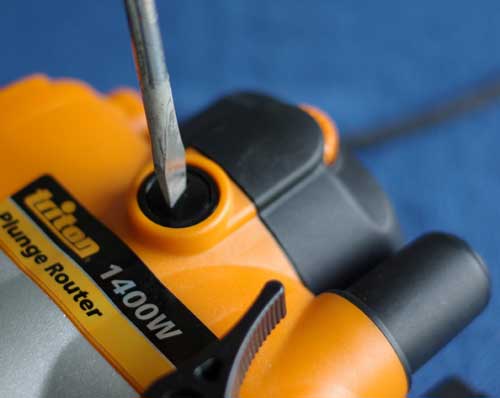
| Next, slacken the screw that
secures the plunge spring cap
(TRA070).
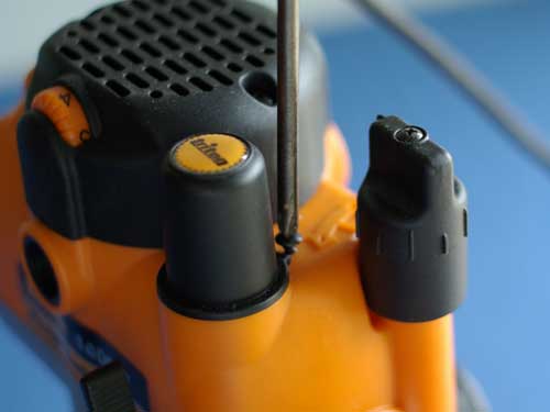
Ensure that the router is at the top of its travel and in rack-and-pinion (winding height adjustment) mode. Remove the spring cap carefully, keeping downward pressure whilst turning to the left sufficiently to release the bayonet fitting. Remove the plunge spring (TRA344). |
 |
|
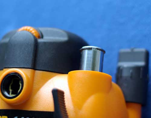 |
Wind the router downwards until
the top of the right-hand post is
above the body sufficient to access
the snap ring, shown here.
Carefully remove the snap ring (TRA325) . Wind the motor body upwards until it separates from the plunge posts and base. |
|
| This shows progress so far.
You can see the motor brushes and caps, the plunge spring and cap, the separated body and base and the plunge post snap ring. |
 |
|
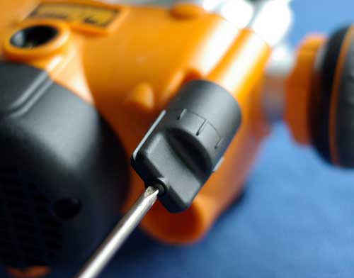 |
Next, remove the M3 X 20 pan head
screw (TRA375) from the top of the
fine adjustment knob, shown here.
Remove the metal "T" shaft (TRA401) downwards from the motor casing, after removing the knob (TRA372&3), spline clutch ring (TRA374), spring (TRA379) and hex washer (TRA377). |
|
| This shows the parts removed, laid out in sequence. | 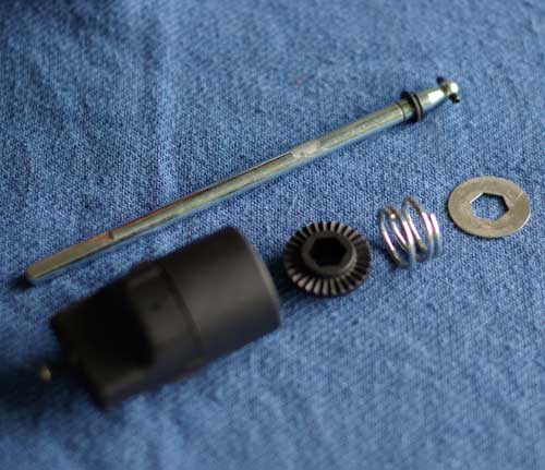 |
|
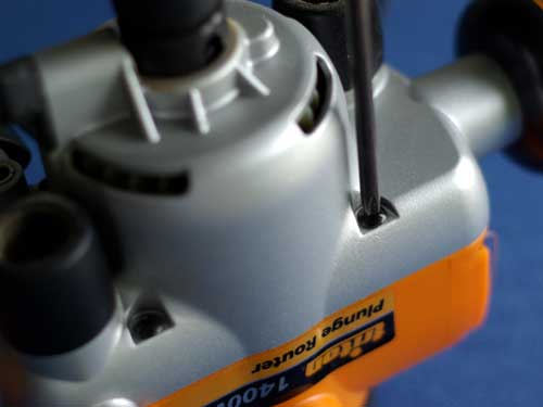 |
Invert the motor casing and remove the four motor body screws (TRA101) that connect the two halves, as shown here. | |
| Ensure that the depth stop (TRA346) is released to its fullest extension, then lock it. | 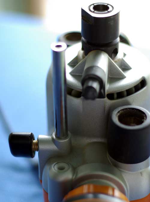 |
|
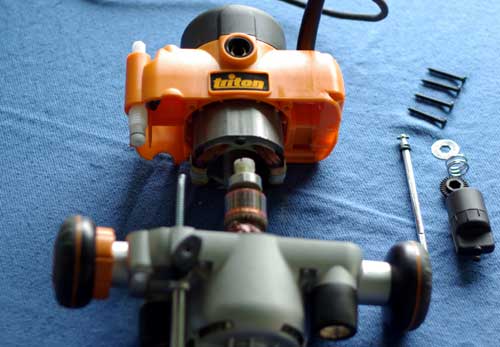 |
Carefully ease the two halves of the casing apart - hold it horizontally to do this and make sure that the depth stop spring (TRA347 - seen here to the left of the motor armature) is not bent in the process. | |
| The main difference between router
models is now revealed, as the fine
adjuster worm drive (TRA378) in the
MOF001 is retained by a metal drag
plate (TRA407) and a 7mm. (M4)
locknut (TRA409).
Here, the drag plate and locknut can be clearly seen, acting on the drive shoulder. Also seen - to the immediate right of the locknut - is the locating post for the plunge depth stop spring. |
 |
|
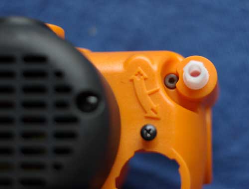 |
The opposite end of the worm drive securing mechanism is a (3mm.) M4 X 35 Socket Head Cap Screw (TRA408), seen here, which is normally obscured by the fine adjuster knob. | |
| The fine adjuster worm gear,
complete with O-ring (TRA406 - 9.6mm
ID x 1.2mm dia.) may now be released
by removing the locknut, then
unscrewing the machine screw. These
parts are shown here (partially
re-assembled) for clarity.
It is important to note that the machine screw does not merely pass through the metal drag plate, but screws into it(*see re-assembly tips, below). |
 |
|
| |
||
"Re-assembly,"
as they say, "is a reversal of
the above process," - BUT
a couple of tips may also help here:
|
||
| We'll now look at dismantling the plunge handle gear assembly. | ||
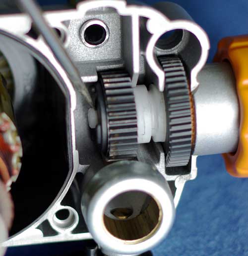 |
The trickiest part of this dismantle is probably removing the E-ring (TRA087), located where the screwdriver blade shows in this picture. | |
| Once the E-ring is removed, the handle can be carefully slid outward. Don't worry if it starts to part as shown here. It will leave the metal worm wheel (TRA376) and the the clutch and pinion assembly (TRA153 & TRA154) behind. These can be removed for cleaning. | 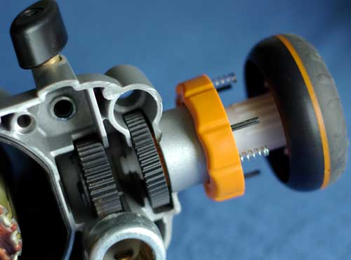 |
|
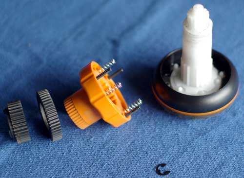 |
This picture shows the progress so far. You can see the E-ring at the bottom of the picture, then (from the left) the clutch & pinion assembly, the worm wheel, the Micro Release Ring (TRA148) assembly and the outer handle (TRA139) assembly. | |
| This picture shows all the
components of the two assemblies.
Bottom line (from the left): clutch,
pinion, worm wheel, micro release
ring (complete with three roll pins
TRA149) and three release ring
springs (TRA090), then the E-ring.
Above these is (from the left) the plunge handle shaft (TRA147), the plunge handle clutch shaft (TRA150) complete with outer spring (TRA152), the clutch shaft inner spring (TRA151), the plunge handle outer rubberised section (TRA139) and the plunge handle inner section (TRA140). Finally, at the top (from the left): the transparent plunge handle lock-out (TRA146) and the plunge select button assembly (shown in parts immediately below). |
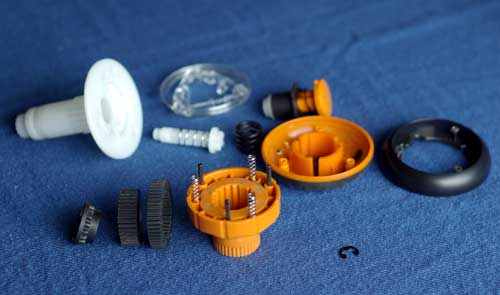 |
|
 |
This picture shows the select
button assembly in detail.
From the left, you see the select push button (TRA141), the select button spring (TRA142), the plunge handle stator (TRA145), the plunge handle rotor (TRA144) and the select button screw (TRA143). N.B *see further assembly tips below. |
|
| This picture is looking down on
the re-assembled handle and shaft
(the shaft is pointing towards the
viewer and deliberately out of
focus), so that you can see the
various indentations that are
important upon re-assembling.
There are two sets of three holes in the inner part of the plunge handle which must be lined up as shown. The holes still "empty" are to locate the roll pins in the micro release ring assembly. |
 |
|
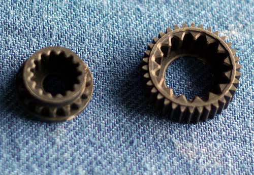 |
This shows the metal clutch and pinion separated for cleaning. | |
| Here, the clutch and pinion are re-assembled prior to being located in the motor housing. This is essential in order to allow the inner shaft to pass easily through when re-fitting. | 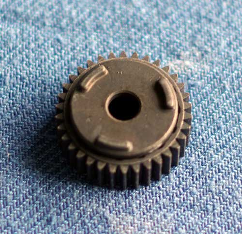 |
|
These further tips may
also help in this section:
Once the E-ring is re-fitted, the router halves are ready to be re-joined.
I hope that this page has been of some assistance in understanding and maintaining the Triton MOF001 router. For a similar page on the TRA001 Router, see here All pictures taken by the author with his Pentax K10D and 50mm f1.7 prime. |
||
| Chuck Assembly
Removal and Replacement
The procedure is the same, no matter what style or type of chuck assembly is fitted. It is carried out with the router removed from the table.
|
||
| The
information in this page is
offered without warranty or
guarantee. The author cannot
accept liability for any form
of injury caused from
following any steps described
herein. Woodworking is an inherently dangerous activity and all safety precautions must be taken, as advised by the tool manufacturer and others. |
||
|
To see dismantling instructions for the larger Triton Router (the TRA001) click here

Pictures and text ©Ray Girling, 2008 - 2026 |
||