Dismantling the Triton TRA001 3¼HP Router
 |
Some preparatory steps are required. For a parts diagram, please
click here
(opens in a new window).
Begin by removing both chip shields (85 & 93 in the parts diagram), if still fitted. Next, remove the screw (75 in the parts diagram) holding the plunge lock lever (74). Remove the lever, then unscrew the brass plunge lock bolt (71). (Although this step is not strictly essential, it prevents problems on reassembly) |
|
| Now remove the screw (30) and the micro adjust knob (31).
This step can be achieved later, but it's easier to do it now. |
 |
|
 |
The five screws visible in this picture can be safely left
alone, as they hold the switch cover assembly to the upper motor
body (for completeness, they're numbers 21 and 22 in the parts
diagram).
Remove the motor brushes, taking care to note their position and orientation. Remove the plunge spring cap (9) and the spring (88 - if fitted). |
|
| Retract the depth stop tube and lock it.
Optional step - access to the variable speed unit (if necessary) requires removal of the two screws (1) and the motor top cover (2). |
 |
|
 |
This picture shows the circlip (snap ring - 87) which must be
removed from the top of the right-hand plunge tube.
Also now visible is the (white plastic) worm shaft of the micro adjuster and the variable speed assembly, which is piggy-backed into the top cover screw locations. |
|
| This shows the front two (partly-removed) coarse-threaded screws which hold the top motor body to the motor housing (picture taken before disassembly from the base unit). | 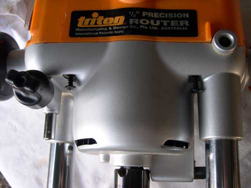 |
|
 |
Wind the top motor body off the base unit, then separate the two
halves by removing the four screws, which are now easily
accessible.
N.B. This is not where they landed after an enormous "boing!" - there was no springing apart - it's just where I laid them out for photography. |
|
| After partial re-assembly - for clarity - this picture shows the
winding mechanism with the clutch (45) disengaged (free plunge
mode).
As the router is plunged against the spring, the white cog freewheels up and down the rack. |
 |
|
 |
This picture shows the clutch engaged (rack-and-pinion winding mode). | |
| This shows the metal worm wheel (47) and the plastic worm shaft
(34) separated - the shaft rides in a cup formed in the main motor
housing.
You may be able to see traces of wear on the worm shaft. Replacing it (part number TRA036) completely refurbished the micro adjusting mechanism. One of the two bushes can clearly be seen - * see below. |
 |
|
| Now is the time for a good clean, blow out with an
airline, light lubrication, etc.
* Pay attention to the inside of the bushes through which the plunge posts run (76) - they can get caked with a very thin but very hard layer of dust build-up (particularly MDF dust). I highly recommend that you replace the plastic worm gear shaft with an alloy replacement (TRA036) available here. Further dismantling stages for reference:(N.B. refer to re-assembly tips below if just cleaning or replacing worm shaft) |
||
| We'll now look at dismantling the Plunge Handle
Assembly, in the event that any replacement parts are required.
This section covers the earlier "push and twist" plunge selector mechanism. For push-button selectors, see the process for the MOF001, halfway down the page here. |
||
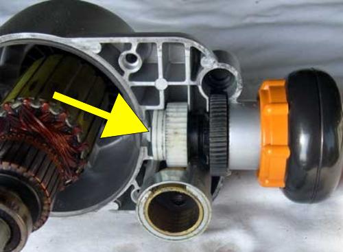 |
Begin by removing the E-ring (44) and metal washer on the inner
end of the assembly (arrowed).
The handle assembly can now be carefully slid outwards. This will leave behind the white plastic clutch plate (45), white plastic pinion (46) and the black metal worm wheel (47). These can be removed for cleaning. Note their orientation. |
|
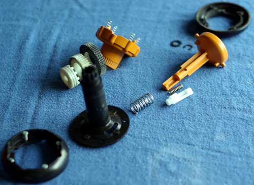
| The handle can now be further dismantled if necessary. This
picture shows all the components laid out. From the bottom corner,
diagonally, these are:
The plunge handle inner section (52) In the back row, from the left are the clutch plate, pinion, worm wheel and the release ring (55) with its four springs (54). |
 |
|
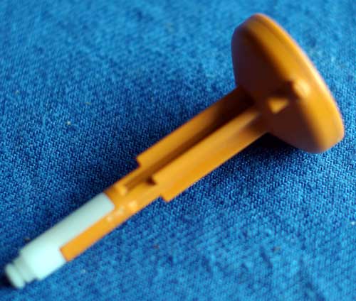 |
One of the fiddly parts of this process is to re-assemble the
plunge selector rear section (white), complete with its spring,
back onto the orange plunge selector.
This is what it should look like when correctly re-assembled. |
|
| Next, the plunge selector spring (48) is slid onto the selector. |  |
|
 |
This picture is taken looking down on the re-assembled handle
assembly. The shaft is towards the viewer and deliberately out of
focus.
This is to show the orientation of the plunge handle inner section, relative to the underside of the orange selector. The four indentations are to seat the four release ring springs. |
|
| Here are the clutch plate and pinion, separated for cleaning. |  |
|
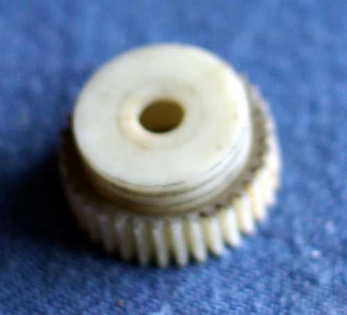 |
Here is the clutch and pinion assembly, prior to
re-installation. They need to be re-fitted to the motor body,
together with the black metal worm wheel before the handle
assembly is slid through them.
Re-fit the E-ring and washer and the job is complete. |
|
Re-assembly is fairly straightforward, with one or
two things to look out for:
I hope that this was of some assistance in understanding how this rack-and-pinion mechanism and related components work. |
||
| Chuck Assembly Removal and Replacement
The procedure is the same, no matter what style or type of chuck assembly is fitted. It is carried out with the router removed from the table.
|
||
| The
information in this page is offered without warranty or
guarantee. The author cannot accept liability for any form
of injury caused from following any steps described herein.
Woodworking is an inherently dangerous activity and all safety precautions must be taken, as advised by the tool manufacturer and others. To see dismantling instructions for the smaller Triton Router (MOF001) click here Pictures and text ©Ray Girling, 2007-2026 |
||
